

 Press Automation Control and Monitoring Systems: Historical Perspective
The illustration on the right identifies the major components of a typical mechanical press.The motor/flywheel combination drives the crankshaft, which causes vertical movement of the ram. The material to be stamped is placed between the two die halves.The bottom half of the die is bolted to the bolster, while the top half is mounted to the ram.The part is formed/stamped when the two die halves come in contact with the material and press it. Modern electronic controls help increase press productivity, improve part quality, and protect costly dies and presses from damage. Autotech offers several such controls as discussed below.
 Die Protection / Press Automation System
A programmable limit switch (PLS) provides press-position-based timing outputs for automation functions such as Feed, Eject, and Lubrication. Autotech’s PLS products contain several unique features that benefit press operations. For example, they have built-in motion detection eliminating the need for separate units. Motion detection supports programmable “detect-delay” to allow the press to ramp up to speed without tripping a motion fault.The Reverse-motion-disable feature provides safeguards by disabling outputs if the press moves in reverse direction. Die Protection Systems from Autotech, protect expensive dies from damage by monitoring proper material progression throughout the press stroke.
 Low Cost OSHA Compliant Programmable Brakewear Monitor
For safety reasons, it is important to monitor press stopping time. M1025 Brakewear Monitor allows the user to program a stopping time limit, and activate an output if the press stopping time exceeds that limit. An input is provided to clear brake-time related faults. Additionally a motion detector output is also provided.
Press Load or Tonnage Monitoring
Programmable Load Monitor, Mini PLM M1030-E from Autotech, is one of the best investments in tools for a press. It offers an economical entry into monitoring the Peak Tonnage generated during a Press cycle. Alarm outputs are provided if the Tonnage exceeds preset limits.
 Shut-Height Indication / Control
Shut height of a press is die dependent, and must be set precisely to produce quality parts, and to safeguard dies.The traditional method of Die Setting uses a trial and error approach: the Shut Height is changed, measured using blocks, verniers, etc., and readjusted based on the measurement. This makes Die Setting a time consuming process. Shut Height Indicator products from Autotech eliminate the need for measuring Shut Height. Once calibrated, these products constantly display/monitor Shut Height making die changeover quick. In addition, these products detect any Shut Height drift during operation.
 Rugged Resolver based Technology
Autotech has 30-plus years of experience in applying Resolvers and PLSs in some of the roughest environments in the world. Autotech invented the first microprocessor-based Programmable Limit Switch (PLS) in 1975 to replace electromechanical cam banks. As such, the position transducer had to work reliably in outdoor settings from Alaska to the Mohave desert or get mounted on an End Conversion Press in a two-piece can manufacturing plant, where the shock and vibration during those days was such that even the plant floor had to be rebuilt every six months. The PLS also had to be highly accurate and super fast in its response time.
Against this background, Autotech has continuously enhanced its Resolver and PLS technology and is a world leader in these products with an installed base of over 100,000 systems worldwide.
Resolver Basics
A Resolver is essentially a rotary transformer, having one rotor winding and two stator windings. The stator windings are located 90 degrees apart. Either rotor or stator winding can be used as primary. Typically, the rotor winding is driven by a reference voltage at a frequency ranging from 400 Hz to several KHz. As the shaft rotates, the output voltages of the stator windings vary as the sine and cosine of the shaft angle. See Below:
 The two induced stator voltages are a measure of the shaft angle and are converted to a digital signal in resolver-to-digital decoder. Among various R/D decoding methods available, the two most commonly used are:
• Ratiometric Tracking Converter
• Phase Method Converter
Ratiometric Tracking Converter, Enivornmentally Immune
The circuit features a Type II servo-loop that comprises of sine/cosine multiplier and an error amplifier together with phase sensitive demodulator, error processor, voltage controlled oscillator and an up/down counter. Since the VCO is controlled by an error integrator, the greater the lag between the actual shaft and the digital angle in the counter, the faster the counter will be called upon to “catch-up” or “track” and eliminate the error.
The information produced by this type of converter is always “fresh”, being continually updated and always available at the output. The basis of determining the shaft angle in a ratiometric converter is the ratio between the two stator signals.
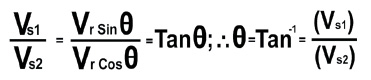
From this relationship it can be noted that the angle is no longer a function of the induced rotor voltage Vr, but rather the ratio of VS1 and VS2. Therefore, variations in the rotor voltage Vr, frequency and temperature are no longer factors in a ratiometric converter. This results in a highly accurate and repeatable resolver-to-digital converter.
Unique Autotech Features
Autotech’s patented resolver decoder technology allows resolver to be as much as 2500 ft. away from the decoder and provides a reliable shaft angle position even under the most challenging operating environment. Additionally resolver signals are short circuit proof.
The phase method converter used by some of our competitors lacks the noise-immunity and speed of a Ratiometric convertor and as such is not used by Autotech.